
Step 1: Open or Reset 3d Studio Max, go to Command Panel, click on Create, click on Geometry and select the Cylinder. Create a Cylinder with this setting: Radius 100cm, Height 8cm, Height Segments 1, Cap Segments 1 and 64 Sides.

Step 2: First thing to do now is to convert your Cylinder to Editable Poly, to do this just right click on it and chose Convert to-> Convert to Editable Poly from the list. Now go to Polygons selection Mode in the Modify tab on Command Panel(shortcut key is 4). Select the top and bottom polygons and apply an Inset by 3cm, press OK(check mark) to continue.

Step 3: Go to Edge selection mode(shortcut key is 2) and make a loop selection. To do this, simply select to edges and press the Loop button(see image below to see what edges to select and loop). After you did this from Edit Edges rollout menu select the little box next to Chamfer and change to amount to 1cm and the segments to 6. Press OK.

Step 4: Go to Polygon selection mode and select the single top polygon. From Edit Polygon rollout menu apply an Inset with amount of 40cm.

Step 5: With the same polygon selected apply and Extrude by clicking the little box next to it. Change the extrude type to Group and the amount to 8cm.

Step 6: Apply another Inset with amount of 50cm.

Step 7: Hold down CTRL and click on the Vertex in Selection rollout menu. This will convert your selection to Vertex. You now must have 64 verices selected, apply a Weld to them by clicking on the litte box next to Weld. Change the amount to 10cm, you will see all vertices snap together. If you don't just raise the weld amount.

Step 8: Go to Edge selection mode and make a ring selection. Select one edge and click on Ring(see image below to see what edges to select). Now in Edit Edges rollout menu click on the little box next to Connect. Leave the default setting(1 segment, 0 pinch and slide) and press OK.

Step 9: In previous step we divide some polygons in 2 by applying Connect. Select the top of the new created polygons(see image below). In front view simply click and drag over them or just make a ring selection of the edges, hold down CTRL and click on polygons selection mode to convert your selection. Click on the little box next to Extrude, change the Type to Local Normal and the amount to 15cm.

Step 10: As we did in Step 3 we are going to make a Loop selection of the Edges again. Select 2 edges and click on Loop(see image below for what edges to select). Apply a Chamfer with 1cm amount and 6 segments.

Step 11: Exit selection mode, click on Editable Poly in Modify tab or press 6 on your keyboard. Right click on the screen and click on Hide Selection.

Step 12: Create a Box(Create->Modify in Command Panel)with Length of 15cm, Width of 15cm and Height of 10cm. All segments set to 1. We must move it to the center of the grid. To do this change the coordinates numbers to 0 for X,Y and Z axis from the bottom of the screen.

Step 13: Convert the Box to Editable Poly, go to Polygon selection mode and select the 4 margin Polygons.

Step 14: Extrude the polygons with an amount of 50cm and Type By Polygon.

Step 15: In Edge selection mode select the edges you see selected in the image below and apply Connect with 1 segment, 0 pinch and Slide 75.
Note 1: To toggle between Wireframe and Smooth + highlights press F3
Note 2: To toggle between Edged Faces on or off in Smooth + highlights press F4

Step 16: Go to Polygons selection mode and select the 4 polygons i've selected below and apply and Extrude of 120cm and the Type Group.

Step 17: We now must Target Weld some vertices together. Go to Vertex selection mode, click on Target Weld, after that click on the first vertex then on the second vertex to weld them. See the below image to figure out what's happening.

Step 18: Target Weld some more vertices like you see below.

Step 19: Exit selection mode(6 on you keyboard), right click on your screen and select Unhide All.

Step 20: Select the legs of the table and using Select and Move tool in front view move them down in Y axis direction right below the table top.

Step 21: Move the 4 groups of 4 vertices like i did below. Select the first group of 4 from the right and move the a little bit to the right, the 4 from the left move them a little bit to the left and so on...

Step 22: In edge selection mode select all edges, CTRL+A to do this. Apply a Chamfer with an amount of 0.2m and 1 segment.

Step 23: Exit selection mode and select both the table and the legs. Click and drag over them with the select tool, select and move tool, scale tool or rotate tool. Click on the little square next to "2 objects selected" and change the color to brown or what ever you like.

Step 24: Select the legs, go in Edge selection mode and select the edges i've selected below. Connect them with 1 segment and 50 Slide.

Step 25: In Polygons selection mode select the 4 polygons from the bottom of the legs like i've did below. First we need to apply an Inset of 1.8cm, click OK and after that apply and Extrude with Type Local Normal and amount of 2.5cm.

Step 26: In any selection mode you like click the box next to Attach and select the Cylinder to attach them together.

Step 27: From the Modifier list apply a Smooth modifier and check the box next to Auto Smooth. We are done. Good Job!

3D Modeling Result:
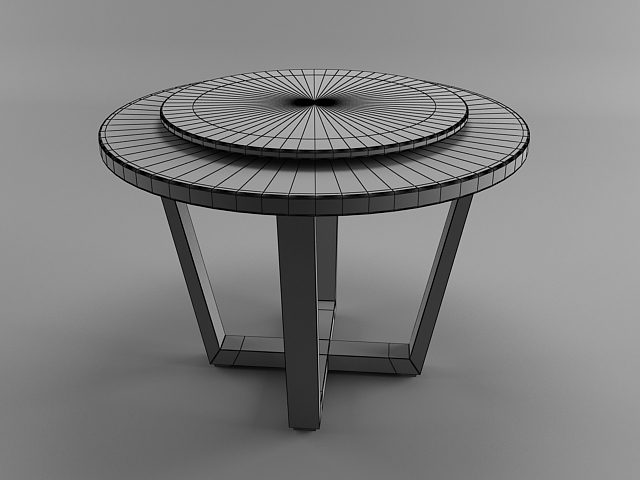
If you get stuck somewhere along this 3d Modeling tutorial don't hesitate to comment and ask me the solution!


