
Continuing with the Mp3 Player 3D modeling tutorial, in this second part you will learn how to create the Earphones. 3D modeling tools such as Extrude, Bevel, Connect, Chamfer, Extrude Edges and Modifiers such as Turbosmooth will be used. After we are finished with this all that is left is to arrange our scene and create the materials and the studio setup. So let's move on.
Part 2 - 3D Modeling the Earphones
Part 3 - Arranging the Scene
Part 4 - Materials, Lights and Render settings
Step 1: To begin our 3d modeling tutorial Open or Rest 3ds Max. In the top right corner, from Create, Geometry create a Cylinder with the Radius of 1.0cm, the Height of 0.3cm, change the Height Segments to 2, the Cap Segments to 8 and the Sides to 18. Move it to the center of the Grid. To do this, simply select the Select and Move tool and change the X,Y,Z to 0 in the bottom of the screen.Part 3 - Arranging the Scene
Part 4 - Materials, Lights and Render settings

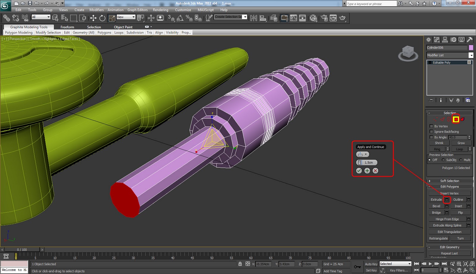
Step 2: To convert the cylinder to Editable Poly right click on the screen, Convert to > Convert to Editable Poly. From the Modify tab in Command Panel go in Polygon Selection Mode(shortcut key "4"). Now select the polygons I've selected(hold down CTRL to select the one by one) and click on the little square next to Extrude. First apply an Extrude of -0.005, click on the Plus sign to apply it, then change the Extrude amount to -0.03 an click the check mark to finish.

Step 3: In Perspective view go to the other side of the cylinder. Change the selection mode to Edge(shortcut key "2"), select the edges I've selected, select one from each line and click on Loop, hold down CTRL and click on Remove. You must hold down CTRL because you need to remove also the vertices associated with the edges.

Step 4: In Bottom view(to change the viewport press "V" on your keyboard) select the Polygons I've selected and move them up a little bit like you see below using the Select and Move tool.

Step 5: Now in Front view move the same polygons down.

Step 6: Select the Select and Scale tool, click on Percent Snap Toggle to activate it and scale down the polygons in all 3 X,Y,Z axis to 90. The center yellow triangle must be highlighted to scale down correctly.

Step 7: Extrude the Polygons with an amount of 1.0cm.

Step 8: Change the selection to Edge and make an loop edge selection. Select on edge and click Loop. Chamfer the edges with an amount of 0.1cm and 2 Segments.

Step 9: Go in Vertex selection mode(shortcut key "1") and select the Vertex in the center. From Soft selection rollout menu check the box for Use Soft Selection. Change the Falloff amount to 0.5cm and the Bubble to 0.75. Using the Select and Move tool move it don a little bit until you have a nice curve. When you're done uncheck the box for Use Soft Selection.

Step 10: In Edge mode select the edges I've selected below. Use the Loop tool again. Chamfer the edges with an amount of 0.01cm and 2 Segments.

Step 11: Like we did in step 9 select the center Vertex again and by checking use Soft Selection box and changing the Falloff to 1.0cm move it up, not to high, to create a nice curve.

Step 12: Press 2 to go to Edge selection mode and select the edges you see selected below using Loop.

Step 13: Click on the little box next to Chamfer, change the chamfer amount to 0.07cm and the Segments to 2 and click on the Check mark for OK.

Step 14: In step 2 I've forgot to tell you to Detach the polygons, so we'll do it now. Select the Polygons again and from Edit Geometry rollout menu click on Detach, check the box for Detach as Element and click OK.

Step 15: Continuing with our 3d Modeling Tutorial we will create a new Cylinder in the Left view with a Radius of 0.275cm and the Height of 1.5cm. Change the Side number to 12. Align it like I've did.

Step 16: Convert the Cylinder to Editable Poly. Right click on it Convert to > Convert to Editable Poly. In Polygons selection mode select the two polygons from each end of the cylinder and Delete them by pressing Delete on your keyboard.

Step 17: In Border selection mode(shortcut key "3") select the border, hold down SHIFT and move it to the left to copy it.

Step 18: Using Select and Scale tool scale the border up a little bit like you see below.

Step 19: With Select and Move tool copy the border again to the left by holding down SHIFT.

Step 20: Scale down the border in all 3 X,Y,Z axis to 60(see the bottom of the screen). Remember, the center triangle must be highlighted when you scale in order to scale down in all 3 axis direction.

Step 21: Like we did in previous steps copy and scale down two more times.

Step 22: With the same border selected click on Cap in Edit Borders rollout menu.

Step 23: Selecting the Polygons resulted from the caped border Inset it with an amount of 0.03cm.

Step 24: Extrude the same polygon with an amount of -1.0cm.

Step 25: In Edge selection mode make an Edge loop selection and Chamfer them with an amount of 0.005cm and 2 Segments.

Step 26: From Edit Geometry rollout menu click on Attach first and then click on the first create cylinder to attach them together.

Step 27: After you make an new edge loop selection Chamfer them with an amount of 0.1cm and 2 Segments.

Step 28: Again make and edge loop selection and Chamfer the edges with an amount of 0.01cm and 2 Segments.

Step 29: See image below and make a Ring selection of the edges. Select one edge and click on Ring. After the click Connect to connect them together.

Step 30: Now with the edges resulted from Connect selected go in Edit Edges rollout menu and click on the little box next to Extrude. Change the Height to -0.1cm and the Width to 0.005cm.

Step 31: The next step of this 3d Modeling Tutorial is to apply a Turbosmooth modifier. So, from the Modifier List select the Turbosmooth modifier, change the Iterations to 2 and check the box for Isoline Display.

Step 32: With one Earphone finished in the next steps of this 3d Modeling tutorial we will create the jack.
Create a new Cylinder with a Radius of 0.4cm and a Height of 1.2cm. Change the Cap and Height Segments to 1 and the Sides to 12.

Step 33: Convert this Cylinder to Editable Poly like we've did in previous steps. Select the end Polygon and click on the box next to Bevel. Change the Bevel Height to 1.7cm and the Outline to -0.17cm, click the Check mark for OK.

Step 34: Inset the Polygon with an amount of 0.05cm.

Step 35: Using the Select and Scale tool scale down the polygon in the Z axis direction.

Step 36: Extrude the Polygon with an amount of -0.1cm. After that Delete it.

Step 37: Select the edges you see selected bellow using Loop and Chamfer them with an amount of 0.005cm and 1 Segment.

Step 38: Now select one edge and click on Ring to make a Ring selection.

Step 39: Connect the Ringed edges with 9 Segments.

Step 40: Select the 5 edges you see highlighted below and click on Ring. After that hold down CTRL and click on the red square to convert the selection to Polygons.

Step 41: Inset the polygons with an amount of 0.005cm.

Step 42: Extrude the polygons with -0.1cm. Change the Extrusion type to Local Normal.

Step 43: Inset the polygons again with 0.005cm.

Step 44: Select the following edges using Ring and Connect them with 2 Segments and a Pinch of -20.

Step 45: Select the following edges and Connect them with 4 Segments.

Step 46: Extrude the edges resulted from connect with the Height of 0.005cm and Width of 0.025cm.

Step 47: Chamfer the extruded edges with 0.005cm and 1 Segment.

Step 48: Now select the polygon from the other end of the jack. Inset it with an amount of 0.1cm.

Step 49: Extrude the Polygon by 0.1cm.

Step 50: Inset again by 0.1cm.

Step 51: Extrude the Polygon with 1.5cm.
Step 52: Bevel the polygon with Height of 0.1cm and the Outline of -0.07 cm.

Step 53: Now Inset the polygon with an amount of 0.1cm

Step 54: Select the following edges you see selected below. Again, use Loop.

Step 55: Chamfer them with an amount of 0.005cm and 2 Segments.

Step 56: As you learn in previous steps add a new edge by using Ring to select the edges and Connect by adding the edge. Change the Slide to 50.

Step 57: Chamfer the edge resulted from connect with 2 Segments and 0.005cm.

Step 58: From the 3 loop edges select the one in the left and scale it down using the Select and Scale tool in the Z and Y axis direction.

Step 59: Chamfer the edge with 2 Segments and 0.005cm.

Step 60: From the Modifier List select the TurboSmooth modifier, change the Iterations to 2 and check the box for Isoline Display.

Step 61: I've notice that I've forgot to chamfer some edges so select them change the amount to 0.005cm, the Segments to 2 and click the check mark for OK.

Step 62: Select both, the jack and the earphone, click and drag over them or press "H" to select from scene, select them both using CTRL and press OK. Click on the little colored square in the top right corner, select your desired color and click OK.

Step 63: To continue with this 3d Modeling Tutorial select the Earphone. Hold down Shift and move it down to Clone it. From Object select Copy, for number of copies make 1 and click OK.

Step 64: Here is what we've got so far from this 3d Modeling Tutorial:

Step 65: In the next steps of this 3d modeling tutorial we will create the Earphones cord/line/cable. So, go to Create, Shapes and select the Line. Create i line like I've did by click on the screen. Right click to end the line. Remember this is not the exact size of the cable, I'm only showing you how to do it. So you want to make it larger.

Step 66: Select almost all the vertices except the end ones. 1 one from the top and, 2 from the bottom end and convert the to Smooth or Bezier, as you wish. I've chosen Smooth but with Bezier you will have more control over you vertices by using the handles. Now move them around to have some nice curves.

Step 67: In the Modify tab, form Selection mode select the Spline. Now select our spline from the viewport. Apply an Outline of 0.08cm but I've notice this is kind of a small amount, so make it 0.15cm or 0.2cm.

Step 68: In Segment selection mode select the two segments for each end and Delete them.

Step 69: Select the two vertices from the end and move one in every earphone. Change the vertex mode to Bezier corner and using the handles adjust the position.
Note: You can see in the left view that the cable of the earphone is very flat, so if you insert in into a scene you will want to move the vertices around to have some curves.

Step 70: For the Final step of our 3d Modeling tutorial go to Rendering Rollout menu and check the box for Enable in Renderer and Enable in Viewport. Make the type Radial, Change the Thickness to 0.078cm or higher if you chose a higher Outline amount in previous step.

Step 71: We will have two extra steps for this 3d modeling tutorial. Since we've applied Turbosmooth we want or Objects to formed by quads. Select the earphone and select every other edge and click Remove like you see below. Do the same thing for both of the earphones.

Step 72: To the exact same thing like we did in step 71 only this time on the other side.

Good job. This 3d Modeling Tutorial of the Earphones is done. In the next part we will arrange the Objects in scene. Here is our 3d Modeling result so far:

Next part: Mp3 Player - Arranging the Scene
Use the comment form below if you have any problems following this 3d Modeling Tutorial.


0 comments:
Post a Comment