
This 3d modeling tutorial will show you how to create a very detailed Soda Can in 3ds Max 2011. The shape of the Can is similar to those of energy drinks. The most used 3d modeling tools will be Chamfer, Extrude, Bevel and Inset. Modifiers like Turbosmooth and Shell will also be used. So, let's start this 3d modeling lesson.
Step 1: To start this 3d modeling tutorial Open or Reset 3ds Max. From Create, Geometry create a Cylinder with the Height of 14cm and the Radius of 3cm. Right click on the Cylinder and select Convert to>Convert to Editable Poly.

Step 2: From the Modify tab click on Polygon icon in Selection rollout menu and select the bottom polygon. Click the little box next to Bevel, change the Height amount to 0.2cm and the Outline to -0.2cm. Click the check mark for OK.

Step 3: Extrude the same polygon with an amount of 0.2cm.

Step 4: Inset that polygon with an amount of 0.1cm.

Step 5: Again, extrude the polygon only this time change the amount to -0.2cm.

Step 6: Bevel the selection with a Height of -0.2cm and an Outline of -0.5cm.
Note: If you make more than one Bevel, instead of clicking the check mark for OK you can click the plus sign to apply and make more bevels.

Step 7: Bevel again, only this time change the Height to -0.1cm. Leave the Outline to -0.5cm.

Step 8: With the same polygon selected, click the Inset button, change the inset amount to 0.5cm, click 2 times on the plus sign to apply the inset two times, after that click on the check mark for OK and a third inset.

Step 9: To convert the selection to Vertex hold down CTRL and click on the Vertex icon.

Step 10: With the vertices resulted from the conversion selected click on the Weld button and change the amount to 0.25cm. You will now see all the vertices snap together as one.

Step 11: Change the selection mode to Edge, select every other edge and click on Remove.

Step 12: Select the highlighted two edges an click on Loop to make a loop selection.

Step 13: Chamfer the selected edges with an amount of 0.025cm.

Step 14: Make a Loop selection like we did in step 12 and chamfer the edges with an amount of 0.1cm.

Step 15: To continue this 3d modeling lesson select the top polygon and Bevel it, change the Height to 0.2cm and the Outline to -0.2cm.

Step 16: Extrude the same polygon 2 times with an amount of 0.2cm.

Step 17: Inset the selection with an amount of 0.1cm.

Step 18: Extrude the selection with an amount of -0.3cm

Step 19: Inset with an amount of 0.15cm.

Step 20: Bevel the selection with a Height of 0.15cm and an Outline of -0.05cm.

Step 21: Inset the polygon 2 times, first with an amount of 0.1cm and second with an amount of 1cm.

Step 22: To be more accurate with the 3d modeling example we need to make the can "lip" a little bit thinner. So select the polygons you see selected below, Use Selection Center, right click on the Select and Scale tool, change the Offset:World to 103 and press Enter.

Step 23: Now select the outer polygons and click on Extrude button. Change the extrusion type to Local Normals and the amount to 0.02cm.

Step 24: Make a Loop selection of the following edges and Extrude them with a Height of -0.02cm and the Width 0cm.

Step 25: Make another edge loop selection and chamfer them with an amount of 0.1cm.

Step 26: In this 3d modeling step we will fix the Can some more, select the top middle polygon and press Grow the selection 3 times. Scale the selected polygons using the Select and Scale tool to 105 in the X and Y axis direction.

Step 27: In Vertex selection mode, using the Select and Move tool arrange the vertices like I've did:

Step 28: Now select the polygon and move it down using the Select and Move tool, after that delete it.

Step 29: In Edge selection mode select the edge you see selected below, first click on Ring to make a ring selection and after that click on Connect to connect the edges together.

Step 30: Using the Select and Move tool move the vertices until you have something like below. Enable Edge in Constraints. With this option enabled you can only move the vertices along the edges.

Step 31: Change the Constraints to Nove. Select the following edges and Extrude them with a Height of 0.075cm and a Width of 0.125cm.

Step 32: Now select these two edges and Remove them.

Step 33: To finish the 3d modeling of the can from the Modifier List add a Turbosmooth modifier and change the Iteration to 2. Check the box for Isoline Display. We are done with the 3d modeling part of the can. In the next 3d modeling steps of this tutorial we will create the opener.

Step 34: In this part of this 3d modeling tutorial we will create the can opener. From Create, Geometry create a Plane with the Length of 2.5cm and the Width of 1.5cm. Change the Length segments to 4 and the Width segments to 2. Using the Select and Move tool position the plane right on top of the can.

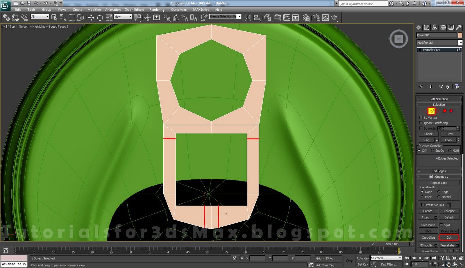
Step 35: Convert the Plane to Editable Poly, go in Edge selection mode and using the Cut tool make the cuts you see below.

Step 36: In Vertex selection move select the two vertices I've selected and Chamfer them with an amount

Step 37: Delete the polygons resulted from the chamfer of the vertices.

Step 38: Arrange the vertices using the Select and Move/Select and Scale tool like you see below.

Step 39: In Edge selection mode make 4 new Cuts.
Step 40: Now add Shell modifier for the Modifier List, change the Inner amount to 0.05cm and the number of Segments to 2.

Step 41: Convert the object to Editable Poly once again to collapse the modifier, in Edge selection mode make a Ring selection of the following edges and click Connect.

Step 42: Select these 4 polygons and Extrude them with an amount of 1cm.

Step 43: Make a Ring selection for the edges resulted from the extrusion of the polygons made in previous step. Connect the with 1 segments and a Slide of 50.

Step 44: Add a Turbosmooth modifier from the Modifier list and change the Iterations to 2. Check the box for Isoline Display.

Step 45: For the final set of this 3d modeling tutorial create another cylinder and using the Select and Move tool position it like you see below. Change the Radius to 0.2cm, the Height to 0.05cm and the Sides to 48.

Extra 3d Modeling Step(Home work :) ): If you wanna model the inside cap just select the can, go in Border selection mode, click on Cap, Detach the new created polygon inset it to add some geometry, connect the edges and extrude them to make the Bump.
3D Modeling Result:


You know the drill, comment if you get stuck anywhere along this 3d modeling tutorial.


0 comments:
Post a Comment